https://freeenergy-transformer.blogspot.com/2023/10/floyd-sweets-free-energy-transformer.html
Unveiling the Power Source
The demonstration begins with a 120-volt fan, spinning with impressive power, creating a substantial breeze. What makes this remarkable is that the power source behind it is unconventional - negative energy. The setup includes five 100-watt lamps, all brilliantly lit, totaling 500 watts of real power. This power is harnessed from the vacuum, showcasing the vacuum triode's incredible power amplification capabilities.
The Magic of Negative Energy
What's fascinating is that this energy is negative in nature until it reaches the resistive load of the lamps. In the lamps, negative energy is converted into ordinary positive energy, resulting in the production of real heat and light. However, in the circuitry and wires leading to the lamps, there is no heating. It's only in the lamp filaments that heat and light are produced in the traditional sense. This transformation highlights the vacuum triode's unique ability to convert negative energy into positive energy, providing 500 watts of usable power.
When does a Fact become a Fact? I have learnt one thing in my time on the VTA Replication Project, question everything and take nothing for granted. Nothing is Factual until it is proven so.
Maurice Campbell stated: "In 1988, Floyd produced a paper which he considered to be very important."
This paper was Nothing is Something. In the paper "Nothing is Something" by Floyd Sweet and of Course Tom Bearden, statements have been very carefully worded such that only one real meaning can be taken from the actual statement. Today I want to look at the actual meanings and see what we can learn from carefully studying the meanings of such statements. First and possibly the most important statements made are: The principle of superposition states that; "In order to calculate the resultant intensity of superimposed fields, each field must be dealt with individually as though the other were not present". The resultant is obtained by vector addition of each field considered singularly. Consider for a moment the construction of the triode which includes the bifilar coils located within the fields of the two conditioned magnets. When the current in one half of the conductors in the coils (i.e., one of the bifilar elements in each coil) of the device is moving up, both the current and the magnetic field follow the right-hand rule. The resultant motional E-field would be vertical to both and inwardly directed. At the same time the current in the other half of the conductors in the coils is moving down and both the current and magnetic field follow the right-hand rule. The resulting motion E-field is again vertical to both and inwardly directed. Thus, the resultant field intensity is double the intensity attributable to either one of the set of coil conductors taken singularly.
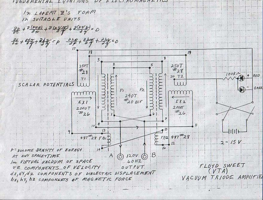
This statement directly relates to this schematic:
I think its important to practically apply the above quote to the schematic and draw out a new schematic as it is explained. I say this because the explanation does not properly support the schematic. E.G: if one is to carefully think about this: 'At the same time the current in the other half of the conductors in the coils is moving down and both the current and magnetic field follow the right-hand rule' then one can not physically have this occur, in direct opposition the the preceding: 'When the current in one half of the conductors in the coils (i.e., one of the bifilar elements in each coil) of the device is moving up, both the current and the magnetic field follow the right-hand rule' and also at the same time have the H-Field Cancel and the E-Fields add, then one of two things can only occur:
Each Filar in the Bi-Filar Coil is counter wound in the same space to the other Filar.
Or, each Filar in the Bi-Filar Coil is Counter Wound, but in different space to each other.
Further information can be extracted in the following quote (Possibly the second most important):
If the directions of the two signals are such that opposite H-fields cancel and E-fields add, an apparently steady E-field will be created.
Of course, it must be clearly obvious that the 'signals' Floyd is speaking of are not the Magnets! We know the Magnets were in Attraction Mode (North South Facing) and as a result the H-Fields could not have cancelled! Logically, two separate 'signals' must each have a separate source, and at the same time, each source must be in a separate time space. If the sources are in the same time space, then if the H-Fields cancel, then automatically E-Fields cancel at the same time, when an externally applied EMF is impressed. This is very easily proven with experiment. Thus we have a conundrum of the largest kind! We have yet again conflicting information, this time from the horses mouth. Point of view is key to making sense of this.
Remembering that Superposition for Magnetics only is applied to the Vector Forces and x, y and z coordinates' are not placed on the source of the Magnetic Field we then have a possibility come forth.
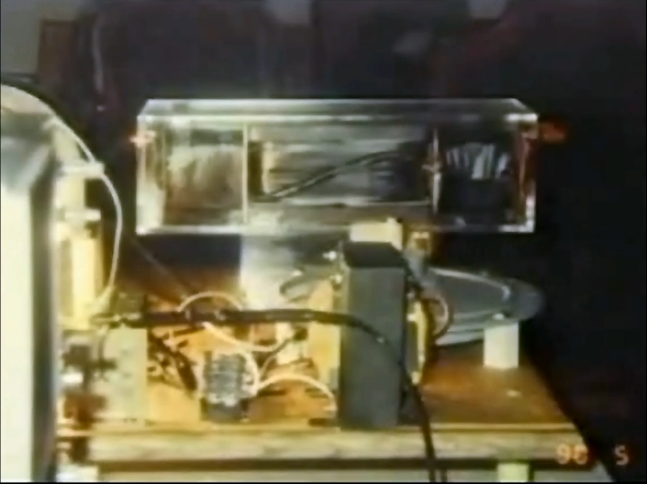
There is a possibility that the Power Coils in the Vacuum Triode Amplifier were not BiFilar by definition at all (the two leads being parallel). Do I have any proof, yes I have good evidence that the Coils had a separate top and bottom Coil on each Power Coil:
Please look carefully at the centre of the power coils on the above pictures. The top two show a clear separation in the Coils from top to bottom. See the Video Here:
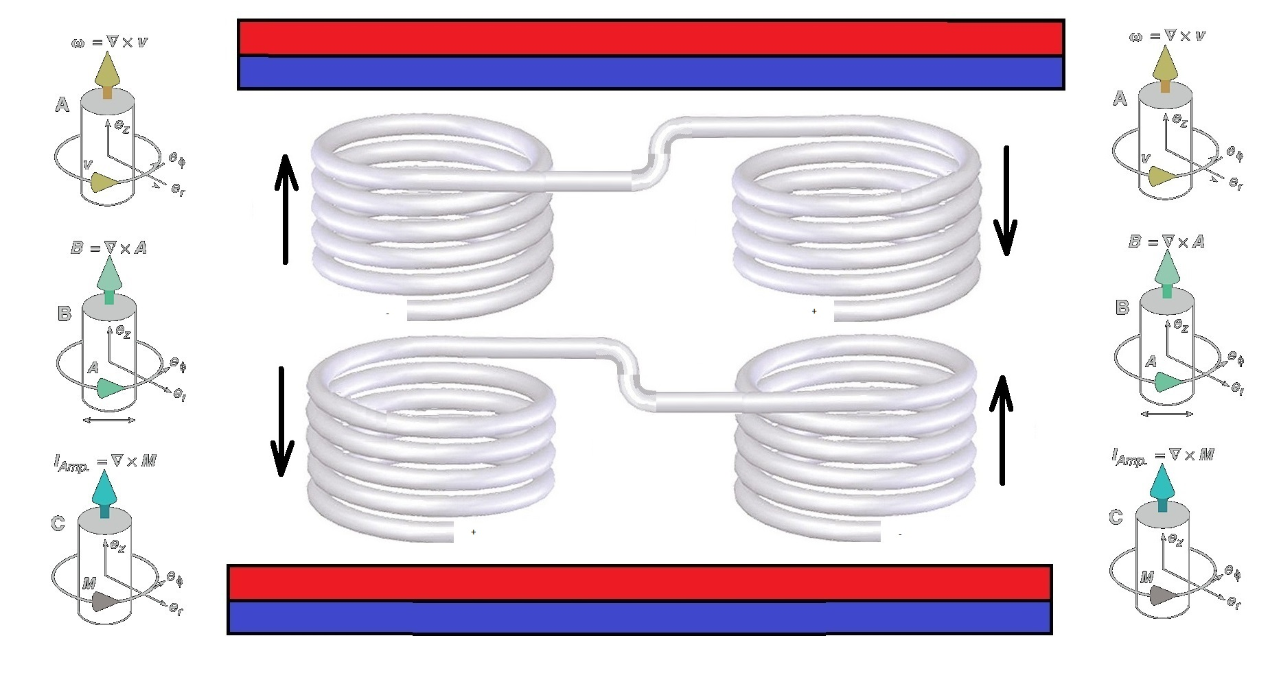
With a little speculation and a little guessing, I have re-drawn the schematic, power coils only, to try to make the above comments make sense from a Magnetics point of View and also a scientific point of view. After all, what's the real definition of the term 'Scalar Potentials' on the schematic above? Its a Scalar North Pole, induced directly by current flow in the two separate power coils. As the vectors cancel in that part of time space, they shoot out at right angles, forming a 'Scalar Potential' being a potential of Magnetic Flux.
Note: Connecting the Output does not induce more current on the input. No Lenz Law Effect between the Input and Output!
If you would like to see the Ultimate Free Energy Device with a COP = Infinity:
🌀 Nikola Tesla's Ether Technology:
💠 Harnessing the power of back electromagnetic fields (Back EMF)
💠 Back EMF generates Lenz's Force in generator
💠 When the output energy is not affected by the Lenz (free) force, a self-powered mechanism will be established from the AC generator head to the induction motor. And the kinetic energy of the induction motor at that time was only supposed to stir the Ether by Nikola Tesla's "Rotating Magnetic Field". That's the mechanism for a Free Energy AC generator - no fuel needed - Self-powered generator.AC generator without fuel:
Free Energy Will Change Our World Forever
👉
Free Energy AC generator
Then apply these concepts to Magnetics!
Bifilar Definition: 1: (Physics / General Physics) having two parallel threads, as in the suspension of certain measuring instruments 2: (Electronics) of or relating to a resistor in which the wire is wound in a loop around a coil, the two leads being parallel, to reduce the inductance ref: https://overunity-electricity.blogspot.com/p/bifilar-coil.html


